As there are only two motorised points in the yard on 'Ruston Quays', I'm fitting some quality Cobalt point motors from DCCconcepts. These are slow-action units using motors and gears, unlike the solenoid motors sold by Peco and Hornby. If you watch a set of real points change, the process takes a few seconds. The motorised throw of the Cobalt units allows us to replicate this. It's also gentler on the track than the sudden change from a solenoid unit.
The Cobalt units have built-in electric switches, which are handy and reliable as I'll make the motor change the polarity of the frog rather than rely on the contact of the point blades. If we want to add lights on the control panel to show the route, it’s another future option.
Aside from the cost, one downside with this sort of motor is its size. You need at least 7.5cm depth under your baseboards to accommodate them - ideally 8cm or more to avoid the risk of snagging the wiring.
Content continues after advertisements
I’ll operate the points from DCCconcepts Cobalt S point levers. They look and operate just like the real thing - squeeze the little lever that operates the catch, then push it across. Although the trains are DCC equipped, the point switches aren't. They are wired to operate either solenoid motors, requiring a pulse of electricity, or slow-action point motors that require a continuous supply of electricity.
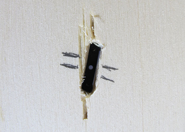
1
The first job is to make a hole for the operating wire to poke through the baseboard. With the point in position, I mark the ends of the tiebar (the long line) and the insides of each rail (short lines). These are then joined up to show where I’m making a hole.
2
The smaller the hole, the neater the finished job will be. Instead of drilling something huge, I’m making a slot by drilling a series of 3mm holes and joining them up - a drill saw bit is perfect for this. If using a conventional bit, waggle it from side to side gently to join the holes. Finish with a file or coarse sandpaper.
3
Putting the point back in position, I’m making sure it can be operated with a wire or thin screwdriver through the hole in the tie-bar. If it touches the sides of the hole, I’ll sand a little more away. Point motors are strong, but avoid unnecessary friction from operating wires rubbing on the sides of the holes.
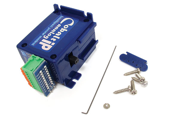
4
Cobalt motors are supplied requiring assembly, although this is nothing more than fitting the operating wire. A self-adhesive pad attaches to the top of the motor and large screws, including a spare, fix it to the bottom of the baseboard.
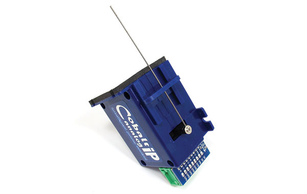
5
The wire pokes through a plastic pivot which can be slid up and down to reduce or increase the throw. In the middle of the casing is a join which represents the centre of the motor throw. I’m not gluing the pivot in place, friction is enough to hold it and will allow adjustment later if necessary.
6
Looking up from underneath the baseboard, I can mark the two positions of the hole in the tiebar. The motor should be screwed to the baseboard with the centreline half way between these. The pivot allows the switching to be off-centre a little, but the closer you can get it, the less strain on the mechanical parts.
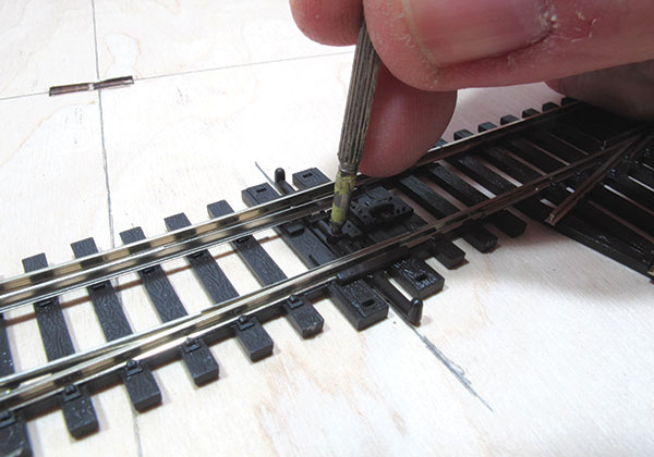
7
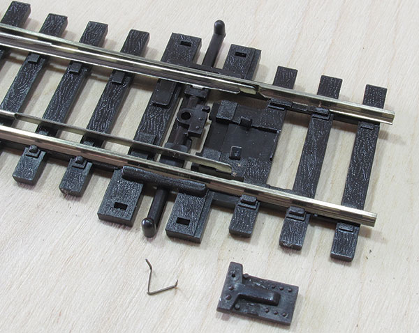
Peco points are fitted with an over-centre spring to lock them in place. Because of this, the blades fly over, defeating the benefits of a slow-action motor. I’m removing the spring by prising the cover from the tiebar and lifting it out with tweezers. The cover can then be replaced and the retaining clips bent back into place.
8
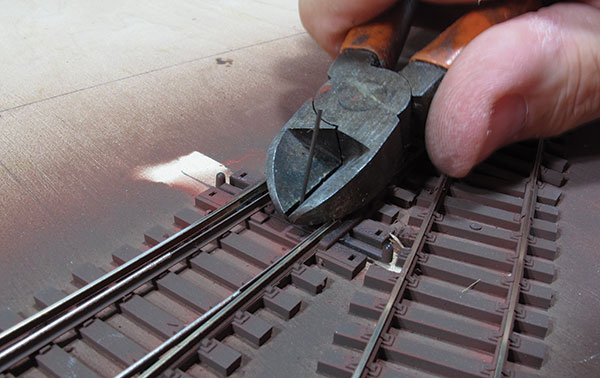
The operating wire is deliberately supplied too long and needs to be cut back close to the tiebar so that rolling stock doesn't catch on it. It's very tough so I’m using some strong cutters. Wear eye protection as the wire will fly off.
9
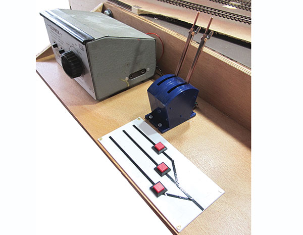
The control panel shelf is made from offcuts of 9mm plywood from my local hardware store. The dimensions aren't critical. This one is 60cm wide and 16cm deep. It needs space for the controller, point levers, a small diagram and a mug of tea.
10
The levers are fitted at the back of the panel and wired underneath with connections made through a multiway plug. A plastic card panel holds the buttons to operate the electronic uncouplers. The lines used are from a car accessory store. The old H&M Clipper controller will soon be replaced with something 50 years younger.
Expert tip
When putting wires into the Cobalt motors, unless you have very thin fingers, use a small screwdriver to push open the catches on the electrical connections.
Your weekly World of Railways newsletter
Are you subscribed to our weekly email newsletter? Don't miss the latest news, reviews, modelling advice and competitions.