Paved surfaces can be one of the hardest things to create convincingly in model form. The textures and colours we witness on a daily basis are usually averaged by modellers to a single colour, be it a light grey for concrete or an off-black for tarmac. Paved surfaces vary in colour. Freshly-laid bitumen is dark in colour, though through dust and wear, it quickly changes to a lighter colour. Concrete is the opposite, often darkening with an accumulation of dirt.
The wrath of Mother Nature takes its toll in changing the appearance of a surface, from freezing water in winter that creates stress cracks and pot holes as does the traffic that travels across these surfaces, to dust in the summer. Heavy Goods Vehicles can soon destroy a thin layer of tarmac or compact it to form a hump in the middle of a road. Perhaps you’re modelling a quiet country lane with weeds in the middle? Or a street outside a house where cars that occasionally leak oil are parked? Don’t forget about drainage, road markings, kerbstones and road signage, too. Adding these details to your model will elevate your paved surfaces to the next level.
For the project layout, being an industrial site, many surfaces are paved and it’ll be a good exercise in honing my tarmac- and concrete-making skills. For good measure, I’m using one of Faller’s Road Systems, too. Somehow, the idea of shunting wagons while avoiding moving road vehicles as they negotiate around the busy site seems quite appealing. Will they, or won’t they clash?
1
The layout is ‘mapped’ using a permanent marker to trace the location of the roads. I altered the track from the prototype slightly to make for more interesting running, so the print-out OS map I’m using serves only as guide.
2
Before adding the hard-standing areas, Code 75 checkrails are installed from spare track. Generously supergluing them into place is sufficient, given these will be buried under plaster that will provide additional support. The rails are cut to length using Xuron shears.
3
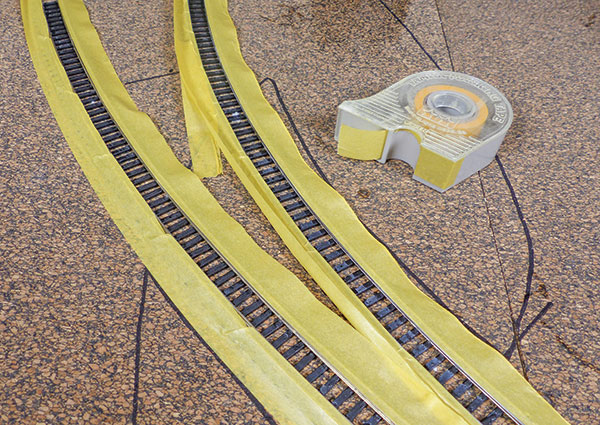
Removing stray plaster from between the rails is a tedious task, so I’m masking between these, beforehand. It’s far easier to remove plaster this way than to scratch along the rails and potentially damage them, later. Valuable cleaning time is saved. You could also try using an old wagon with Tri-ang standard wheels - pushing it along before the plaster dries to leave sufficient clearance for nearer-scale wheelsets.
4
Faller’s Road System contains a small bag of plaster, designed to be used as a thin skim. It doesn’t last on a project of this size which requires a 1-5mm thick covering to create the road slope. A few boxes of household plaster are used to create the road surface.
5
Before the plaster has set, I’m peeling the masking tape away, revealing the track underneath, undamaged and in fine fettle. Adding the plaster takes time, so I’m applying it in small stages, building up layers a little at a time.
6
Sanding the plaster is important to make it level and smooth. It’s important to leave the rails slightly proud of the final height, to prevent wheels from being lifted from the track. Keep the vacuum cleaner to hand, it's messy!
7
Referring to prototype photographs highlights the road edges, which can be cut easily to the desired curvature using a craft knife. The area shown will be filled with ballast, later. Some plaster is removed between sleepers with the knife, too.
8
Plaster debris is removed between running rails and check rails with the sharp end of an old file. Be careful not to damage the fragile track chairs, underneath. Use a wagon to check for running issues and a track cleaner to polish rail surfaces.
9
The junction area of this model is where we shall now concentrate – it has the most variety in the mixture of road surfaces on the layout. Scale Model Scenery’s (LX135-OO) Kerb Stones are cut from the sheet and superglued over the plaster. These are rectangular and must be positioned with the cut lines facing outwards and the taller sides standing upright.
10
The pathway and direction of travel for the vehicles is determined and drawn on the layout with a marker. Crossing the tracks perpendicular is advisable, but not always possible. I’m ensuring that vehicles travel across most of the road surfaces.
11
The sharp end of an old broken needle file is used to carve a pathway for the hardened steel guide wire. It must be below the surface, but only just. Bury it too deep and the magnets on the vehicles won’t follow it. A rule serves as a guide for straight sections, various mixing bowls for the curves.
12
The hardened steel wire will ruin the jaws of cutters, so use an old pair, or a slitting disc in a mini-drill to cut. Powerbond 806 Cyanoacrylate is used to glue the wire in the holes in sections. Old files can be used to prise it into position.
13
Scale Model Scenery’s Kerb Stones are again used to edge a section of the road, as per images of the location. Fine masking tape was used to protect the laser-cut joins from the plaster.
14
With the wire buried, the white van is tested. It’s here that I can explain the many lines on the board. Too narrow a turn radius results in the vehicle losing the wire and crashing. Too sudden a movement, and the vehicle will lose the wire and crash. A lot of fine tuning is required, particularly when the vehicle makes its way across tracks, diagonally. I’m making it this way as I want the gated entrance to the yard to be shared by vehicular and rail traffic. If you want an easier solution, purchase Faller’s laser-cut wooden road templates, available in curve, junction or straight variants.
15
Satisfied that the van works reliably after testing it around the circuit 10 times, a thin skim of plaster is used to fill the trench for the wire. I’m careful around the rails to prevent plaster from fouling the rail/check rail area.
16
Rustoleum Grey Surface Primer is a good start for giving the road areas a faded tarmac appearance. Note the use of masking tape to prevent overspray on the adjacent rails. The absorbent plaster requires a few coats for a more realistic appearance.
17
Road markings are self-adhesive from Scale Model Scenery. I tried its stencils, but whether dry-brushing or spraying, paint worked its way underneath because of a lip to the edges, spoiling the effect. A knife is used to position each, though ensure they are aligned.
18
An even mixture of white and black weathering powders is worked onto the road surface to depict the worn surface. The concrete track infill is masked in preparation of its painting.
19
The road leading to and from the site has a distinctive white-coloured staining from the salt traffic leaving the site. Adding more of the white powder into the dry-brushing weathering mixture achieves this.
20
A combination of Comart 1015 Fertile Soil, black and white weathering powder is mixed to achieve a cream shade of concrete, referring to photographs for reference. The mixture is applied by brush, working carefully up to the edges of the tape.
21
Drains can easily be added to any layout using Scale Model Scenery’s AX013-OO sheet. Many different types are featured, including inspection hatches and water hydrants. I’m colouring the edges of the paper with a felt-tipped pen to prevent the white showing through.
22
A dab of superglue is all that’s required to fix this drain cover into position. Note the concrete-coloured strip, achieved using a can of Rustoleum Concrete Effect. This strip of concrete denotes the edge of the car park, where a fence will be later added.
23
Blending the colours of the tarmac and concrete together requires a lot of patience. I lost count of how many hours it took to dry-brush the tones together with various hues of grey weathering powders. I continued until I felt it looked right, referring to photographs.
24
The final addition, a little ballast, sprinkled in the centre of the junction triangle. This was then followed by a dilute PVA/water mix, though it caused the card kerbstones to delaminate, hence these will be replaced later.