


20 September 2021
|

Here to keep your layout's 'veins' in good order, Paul Moss shares techniques applicable to layouts of all scales and sizes, for successful future operation.
Reliability is something that most of us strive for in our layouts. It means much more than preventing locomotives from stopping or stalling and also includes the capability to quickly diagnose and repair any faults that may occur. This is especially important for those who build and show layouts that regularly travel on the exhibition circuit.
There are many aspects that can affect reliability. A key consideration is ensuring that the electrical power can be delivered from the power source to locomotives and other accessories in a reliable manner. This really means getting some of the fundamental wiring aspects correct from the start and is especially important for those that elect to use DCC.
Electrical reliability can be achieved by addressing many of the aspects detailed here. However, it’s also important to ensure that your locomotives are serviced with clean wheels and clean electrical pick-ups. Regular track cleaning will also assist to maintain reliability, too. Finally, I'll look at the aspects associated with relatively low voltages such as those that power your locomotives and accessories on a layout. If you have a need to deal with mains electricity, please consult a qualified electrician.
Making connections
The more connections that you have on your layout, the greater the risk of electrical issues. However, complex layouts often require multiple connections, so it’s important to ensure that they are reliable. One way to do this is through the use of good quality electrical connectors. Here are some things to consider when selecting connectors for your layout:
Examples of the genre

One option to avoid soldering is a wire splicing type connector. You strip the wire, insert and lock down a lever that holds the wire. These are available in a range of sizes and can have a high current capacity. Typically reusable.

These RS PRO Solder connectors come in a variety of pin counts and also have locking rings and strain relief to ensure that they don't loosen. These require soldering.

Where limited connections are required, the ‘Deans type’ connector is a popular choice for battery-powered radio-controlled car racing. These are also ideal for model railway applications and are designed to handle a significant amount of power. These also require soldering.

Terminal blocks provide cost-effective connections that can be readily reused. Wires don't necessarily require soldering, and they are best suited where there isn’t a requirement to frequently connect and disconnect.
When using a terminal block, add a little solder to the tip of the wire before inserting it. This helps to prevent strands from spreading and the wire from easily pulling out.
Labelling tips

If you have a number of connections under your baseboard, it’s a good idea to label them, particularly if you are using similar connectors throughout. This will reduce the risk of mating the wrong halves together and will also aid in fault finding at a later stage – I’ve made this mistake when rushing to set up at an exhibition!
- A simple and cost-effective way of labelling cables is the use of white electrical tape. The connector identifier can simply be written on with a ballpoint pen and the tape applied to the cable as a flag. This is not ideal if the connector is to be handled frequently.
- Also cost-effective, although much better wearing and no more effort, is the use of heat shrink sleeving. Write or print the connector identifier onto a piece of white paper. Pass a tube of clear heat shrink tubing over the top of the paper label and the cable and shrink it down into position. This is a really neat solution!
- When it comes to adding labels to the baseboard, you can simply write directly onto the timber. I prefer a pencil that I can easily erase should I decide to change the wiring.
Wiring tips
It’s important to choose the right type of wire. The current carrying capacity, number of strands and colour should all determine your choice. Avoid using thin scrap speaker or Bell wire that you may have to hand because this can vary in quality and its maximum current capacity is likely to be limited.
Select wire types based on current rating. This is particularly important on large or DCC layouts where there may be higher current carrying requirements.
Whether you are using clamps, crimps, or soldering in your connections, a dedicated set of wire strippers will reduce the risk of nicking or cutting individual wire strands when you are removing insulation from the end of a wire. Nicks or broken strands can form a stress concentration and subsequent bending back and forth of the wire can create a brittle area, which can result in it easily breaking. If enough strands are broken, the current carrying capacity of the wire will also be compromised in the damaged area.
Ideally, leave slack at the end of each wired connection to enable future rework. Assume that you may need to remake the connection another three times and loop the spare wire for neatness.
Colour coding
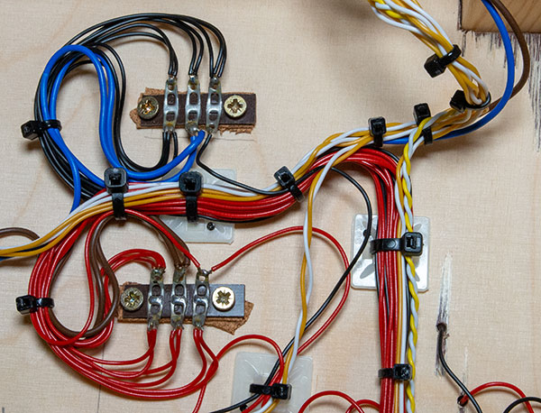
Use a simple colour coding convention for your wires and stick to it across your layout. In this example, blue and brown wires carry the track power throughout the layout. These are terminated onto tag strips close to the track in multiple locations. Red and black wires then provide individual track feeds. Other colours, such as yellow and white, are for point control or other accessories. Plastic tie wraps and cable tie bases keep things secure and organised.

A simple method for tidying wires is to twist individual wires together using a hand drill. Hold one end of the wires in a vice and the other in a hand drill and carefully wind to gain a consistent and neat finish.
Improving proprietary points
Many proprietary points with live frogs transfer the power to the (inner) closure rails via the switch blade rails. This is fine and works well, however, over time, wear, dirt and contamination can combine to degrade the connection between the switch blade rails and the stock rails causing locomotives to stall. It is possible to upgrade your points and make them more reliable with a simple modification before they are fitted into position.

On this Peco N gauge Electrofrog point example, it is necessary to cut the two closure rails as shown within the red circle. This effectively isolates the power from the switch blade rails to the frog.

We now reconnect the power to the closure rails by cutting away a small section of the plastic sleeper base on the underside of the point and solder a short wire link between each closure rail to its adjacent stock rail. This removes any need to draw power from the switch blade rails. This modification can also be undertaken on proprietary points in other gauges and reduces the risk of locomotive stalling.
Track power
Unfortunately, nickel silver rail is not the best conductor for electrical power. It has a higher resistance to electrical conductivity compared to copper. In addition, while connecting power to your track via fishplates is practical, it’s not ideal as you may get an ingress of dirt and other contaminants between the fishplate and the rails, which creates electrical resistance. To ensure the best connection possible, provide as many track power feed dropper wires as possible, and ideally solder these to the rails.
1

2

3

4

Important considerations
|
What to look out for |
What’s important? |
|
Current and voltage ratings |
Large layouts and DCC control may require a high current rating. |
|
Number of pins/connections |
Ensure enough pins for your requirements. Consider if you may need spare capacity (pins) in the future as well. |
|
Strain relief |
Clamps on the connector shell prevent wires being pulled out. |
|
Connector life |
Repeated connection and disconnection will prematurely wear connector pins. Avoid buying exceptionally cheap connectors if you can, its likely to prove a false economy. |
|
Internal connection |
Wires may be crimped or clamped. Many will need soldering. |
Your weekly World of Railways newsletter
Are you subscribed to our weekly email newsletter? Don't miss the latest news, reviews, modelling advice and competitions.