


17 June 2020
|

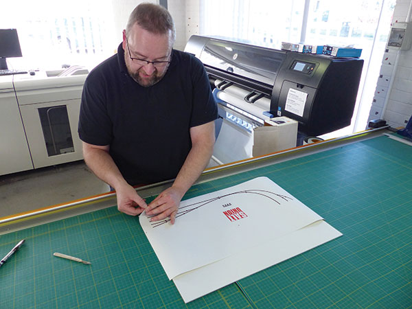
Switches, wires, lights and push buttons combine in these often-complex spaces. Howard Smith outlines considerations to make the heart of your model railway better suit your needs, as he creates a control panel for BRM's 'Runcorn Salt Union' layout.
Control panels were once the sole nerve centre for model railway operation. From here, every aspect of the layout would be controlled. With the advent of DCC, on such-equipped layouts, their use has declined and some DCC layouts have disposed of such panels entirely.
If you’re designing a control panel, it’s easy to be influenced by others’ designs and create a panel that you feel is how a control panel should look, not one that suits your requirements. Ask yourself why you need a control panel – perhaps you don’t. From the control of signals, to points and accessories, all can be accessed at the press of a few buttons on the numerous mid-range and above DCC handsets.
For DC layout users, unless operating a straight piece of track, some form of control panel – even if a solitary switch for a single point – will be required. On such layouts, the control panel remains key to operation because of the need for isolation sections. Signal and point control switches are usually added, some preferring to control each separately, others opting to wire signal control to points or isolation sections, to avoid Signals Passed At Danger (SPADs), declutter their control panel and reduce the number of switches that must be remembered to flick.
An important aspect of control panel design is making it easy to understand. You might understand it, but I feel it’s important that anyone should be able to walk up to it, and, within a minute or so, understand the task each switch performs. I’ve operated layouts where switches aren’t labelled and the guessing game becomes tedious. Take an isolation switch for instance – labelling it should be simple, but don’t write on/off on a label as it’s confusing. Does ‘on’ refer to the isolation being active and power cut, or does it refer to power being applied? Simplifying it to Isolation/Power, or better still, for space on small stickers, Isol/Pwr makes better sense for saving space.
Another important aspect is the role of a control panel in the operation of a layout other than that outlined above. Does the control panel operator act as ‘signalman’, thereby ‘authorising’ the passage of trains across a stretch of line? If so, the role is reversed and on a large layout the control panel operator doesn’t switch signals reactively for the benefit of the spectator, but proactively, indicating to those ‘in-charge’ of a train that they have ‘right of way’. Perhaps the layout is even larger and there is more than one control panel, each operator being responsible for a stretch of track, as per signal boxes. In this instance, is a form of communication between each required, perhaps?
Lastly, and possibly more sympathetic on a present-era model railway, some form of route indication with LEDs might be beneficial. If your layout is to tour the exhibition circuit, don’t be shy of sharing operation with the public, either. Computer control of your DCC layout on a flatscreen monitor with train identifiers, forthcoming trains and route indication can be quite entertaining. Let's get started.
To read more about our office layout, 'Runcorn Salt Union', read our build diary here.
1

2

3

4

5
6

7

8

For more information on DCC controllers, have a look at our guide here.
If you're looking for more advice on wiring your layout, the below articles should help give you a steer.
Wiring your model railway - top tips
Still searching for trackplan inspiration? Our guide gives you simple trackplan suggestions to help you get started.
If you’d like some more advice, take a look at the BRM Techniques page for all our latest guides and advice articles.
