


01 January 2023
|

Martin Ranson scratchbuilds a geared, live steam engine.
I have always enjoyed the challenge of making 'things'. Over many years I have made lots of items, including various working model steam boats.
The idea for a garden railway surfaced about nine years ago. It was rapidly apparent that I knew very little about railway locos, however several small locos have been made, and now chug happily round the garden pulling a few wagons. I watch the locos go past and think 'I made that'.
Powered by a single cylinder oscillator engine, geared down by about 11 to 1, to the main drive wheels, ensures the locomotive cannot accelerate rapidly and then fall off at the first bend on my windy track.
As with most of my projects this one has lots of nuts, bolts and screws so it all comes to pieces easily. The length between buffer beams is 10.6 inches and its weight, ready to run, is nearly 8 pounds.
Boiler and smokebox

This is made from a piece of 2-inch tubing 6.1/4 length. It is all silver soldered. Silverflo 55 is used for most of the joints, and some of the loose parts were tacked on with Silverflo 24. This is high-temperature solder, about 8000 centigrade, very useful for building up a structure without everything falling off in a molten heap.
There is one centre flue using 22mm copper plumbing pipe. There are two types of this plumbing pipe, the thickest is about 0.035 inches and the other is 0.025 wall thickness. The thicker type is definitely to be preferred here. Boiler ends are 2mm thick with a flange. The bushes are phosphor bronze which seems to survive the soldering and usage afterwards extremely well. The threads are all typical M.E. sizes, ¼ x 40, 3/16 x 40 and 5/16 x 32 for the safety valve.
The smokebox is 1mm copper sheet rolled into a circle to fit over the end of the boiler barrel, again the join in this is silver soldered. All the rivets are genuine 1/32 inch diameter with the holes drilled extremely carefully. If I push too hard it breaks too many drill bits! The boiler has been pressure tested to 80 PSI.
Burner

This is also made from phosphor bronze, 3/8 diameter, if I use brass, it is much easier, but some poker burners are silver soldered to a long curved copper plate to ensure the burner touches the inside of the fire tube. Looking carefully up into the end of a fire tube when it was lit and properly warmed up I noticed that the burner tube sometimes ran at dull red heat. This is why the long curved piece of copper is fitted to conduct this heat to the fire tube.
The jet is usually a number 5 Calor gas jet, screwed into a jet carrier which is then screwed into the inside of the burner tube. This makes everything removable for any future adjustment or maintenance.
To make the tube into a burner it obviously needs lots small holes to feed the gas through after it has been mixed with air in the tube. Several methods exist for this, lots of small holes, or narrow slots cut with a hacksaw work just as well as each other. I have been using the slots idea for many years, it is not mine, but I have used the method since I saw it in July 2006's issue of Engineering in Miniature magazine. By grinding off the sides of a junior hacksaw blade, Paul Blake and Brian Wilson produced a slot width of about 0.017 inch (0.43 mm).
Gas Tank

Again another home-made item, my typical size is 1.3/8 inch diameter, this one has a height of 2.5 inches.
As regards filling the tanks, the modern method is to use the Ronson filler valves, but I sometimes find that I struggle to get the tank filled properly on a cold day. Looking at the gas tank, on its top surface there is a large threaded bush. This can be used for my old tank filling system using three separate valves, or it can be swopped for the Ronson type of valve.
Looking at the right-hand side of the tank, there is a copper pipe running down and across to a screw-down valve. This valve has a filter made from fine stainless gauze in the middle so it will hopefully trap any muck heading on its way to the burner. This tank has also been pressure-tested.
Steam cylinder and gearing

The steam cylinder is a homemade double-acting oscillator with a bore of 0.320 inch, and stroke is 0.5 inch. The flywheel is 1.25 inch diameter and must not be too thick or it will hit the boiler. A small section of the boiler cladding has been removed to make sure the flywheel is clear.
The steam admission pipe is at the top and the exhaust pipe is at the bottom of the cylinder. Looking at the flywheel it revolves clockwise, so the gear train was set up to ensure the loco runs in a forward direction. The steam cylinder is at the top of the frames and the drive axle is down at the base, so the necessary gears head downwards. It is arranged to have two stages of reduction with a total of about 11:1.
In the middle of the second stage is a large, white nylon idler gear. This makes installation much easier and simplifies where the gears can be fitted. The second stage gears are 0.8 MOD (approx. 32 DP) and the first stage are 0.6 MOD (approx. 40 DP) The 0.8 MOD gears are probably far too heavy but they were available and sat in the box waiting to be used. The good bit is that they will not break and are very unlikely to ever wear out. When the gears were set for correct meshing I placed a piece of paper between the teeth and then pressed them tightly together. This leaves a small amount of slack for the teeth to wobble slightly as they rotate.
Lubricator
This a typical displacement type with fill at the top and drain at the base. It is quite large, but it was a spare that I had previously made.
Note that the cross-bar is threaded at each end for a cone union. Made this way there are no lengths of copper pipe flapping in the breeze which makes machining awkward. Drilling the small hole in this cross-bar is very easy as the lubricator body can then be fitted in a self-centring lathe chuck. A centre drill is used first to make a small dimple in the cross-bar, then the hole is drilled gently using a very small bit, 0.020 inch or 0.5 mm. in diameter. Done like this, the hole is centred and pointing directly upward. Very handy for any future maintenance.
Pressure gauges and safety valve
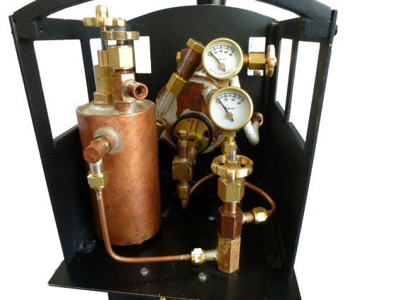
Looking into the cab, you can see two pressure gauges, one of these obviously measures the boiler pressure and the other one is used to measure the gas pressure arriving at the jet. Several people have told me this is not needed, but it is extremely useful for when the gas does not flow properly because of a blockage somewhere in the gas line. A few moments of thought will tell you where the fault is. The safety valve is a standard Roundhouse type lifting at 40PSI and the running pressure is about 25 PSI. The thread is 5/16 x 32 TPI. It has been said to me that many people are much happier to see a Roundhouse safety valve rather than any other.
Bodywork
The cab is made to be easy to remove, there is one steam pipe which unscrews very easily, and four bolts to unscrew from below the cab floor, one in each corner. With the cab removed there is easy access to everything on the boiler backhead. The gas tank is on the left and has a copper pipe running down and then across to a vertical control valve.
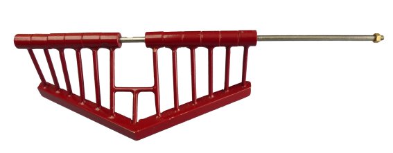
At the front, a cowcatcher is fastened in place with a long bolt across the top. Assembled using a mix of soft solder and silver solder, the materials used were brass rod and brass bar, all assembled on the long bolt. The long bolt allows the front edge to lift up for when the loco is placed on the track with the front end pointing downwards instead of level. This is hopefully to save any damage. The front coupling hook is fitted through the centre of the cowcatcher frame.

The chimney is formed from copper sheet, annealed and slowly bent around a tapered wooden former. The long join was then silver-soldered with Silverflo 24. The base was added as a parallel-shaped piece of brass tube whose diameter was made to match the copper tube fastened into the top of the smokebox.
A headlamp bracket is made of brass sheet and is silver-soldered in place. To make the actual headlamp, some copper sheet was annealed and bent into a box shape around a length of 5/8 inch square steel bar. The plastic lens was machined and filed roughly to shape on the lathe and then polished up with finer and finer grades of emery whilst is was spinning. The finest grades were used “wet”. The finished box shape is obviously hollow and makes a perfect support for an LED. I used a yellow type which I thought looked more authentic than a white one. The LED is fitted up through the box base, its two wires are bent at 900 to point the light out of the headlamp front through the lens. Some very tiny NIMH cells were bought, and then fitted into a battery box on the front right side of the loco. The box is thin brass sheet folded up to shape round a piece of hardwood, the lid is detachable for access. To get the two wires up to the headlamp a length of brass tube is used. Remember that most LEDs are polarity conscious so make sure the 2 wires are different colours.
Dummy cylinders

Because the cylinders are non-powered, I wanted to avoid them causing any unnecessary drag. So they just simply have a 1/8 inch pretend piston rod running through them, the coupling rods are lightweight to keep the mass down. The cylinders should be a larger diameter, but some 5/8 inch brass rod was available, so it was used.
A flat brass plate was soldered to each of them, this was drilled to allow holes to be marked
through the frames for 2 mounting bolts.
Wheels and front suspension
Driving wheels came from Roundhouse and are classed as 33mm in diameter, their code is WD. The small wheels have a diameter of about 16 mm, each one is free to rotate on its axle. The idea was to remove the small amount of drag caused by a pair of wheels on fixed axles when the loco goes round a corner. The four small front wheels are mounted on a bogie. To make sure it is carrying some of the loco weight there is a coil spring pressing down on the bogie centre. When I set it up I used two similar pairs of kitchen scales and kept adjusting the spring until there was about 2.7 pounds weight on it. The remaining 5 pounds weight is carried by the 4 large wheels.
Conclusion
This was a thoroughly enjoyable project, none of it is scale and it used up various items I had already made. I have learnt a bit more about building locos and this one works very happily. Happy steaming!