29 July 2019
|
 Create a DC loop
Adding a return loop to your layout increases operational flexibility, but can create electrical problems for the uninitiated. Howard Smith solves the puzzle...
Reversing loops are useful for changing the direction of trains without requiring the operator to handle rolling stock. In two rail systems, a reversing loop is often avoided because of installation or wiring complexities and without a clear understanding of what it entails, the track supply can be short-circuited. So, if you aren't keen on continually picking up locomotives on your casettes but you don't have room for a continuous circuit and you're a fan of regular running of trains, perhaps it's a solution for you. Here’s a selection of issues that may arise when using reversing loops on a two-rail DC system and how they can be overcome.
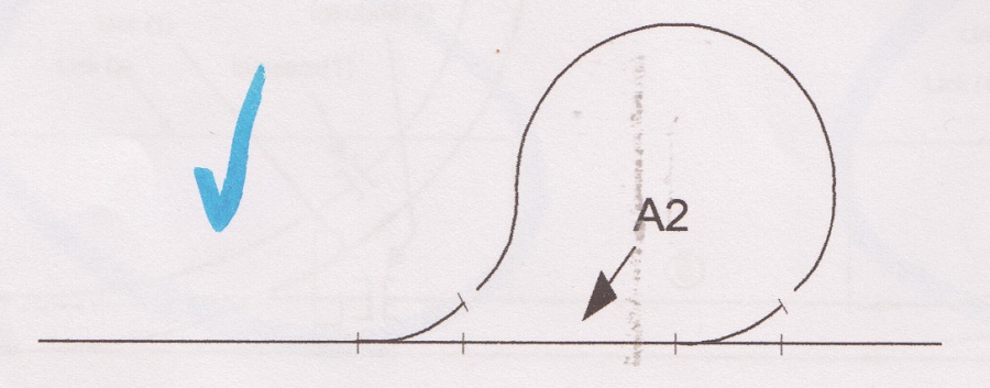
A Simple Loop
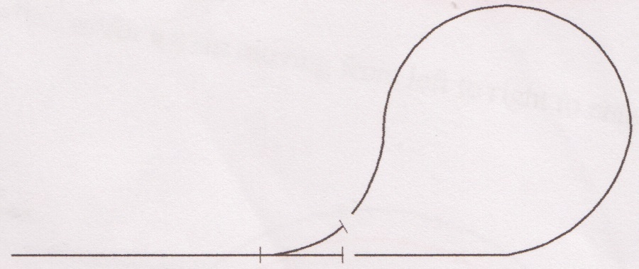
This basic loop requires a single point. A left-hand variant is used for the illustration, but a right-hand or ‘Y’ would work as well, subject to layout requirements. Regardless of whether the points are Insul-frog (insulated frogs) or Electro-frog (powered frogs) some rails in the loop must be isolated from those on the main track. In addition, a changeover switch is required. The wires are coloured differently to indicate the two poles.
Operation
A train approaches the loop, moving from left to right along the straight track. The point is set to deviate from the running line and the changeover switch is set to keep the track polarity in the loop the same as on the main line, allowing the train to enter the loop smoothly. Beyond the isolators at heel of the point, the rails are of opposite polarity - without these there’d be a short circuit.
.jpg)
When the train has entered the loop, the controller is returned to zero, and the point and two-way switch are changed. The controller is turned in the opposite direction. Without the changeover switch, it wouldn’t be possible to match the voltage polarities of the rails within the loop to those of the main line. Reversing the controller and changing the changeover switch ensures the polarity of the voltage applied to the rails in the loop is correct. When the train rejoins the main track, its direction is opposite to what it was initially, so the polarity of the supply to the rails of the main line has changed.
2. A loop with points
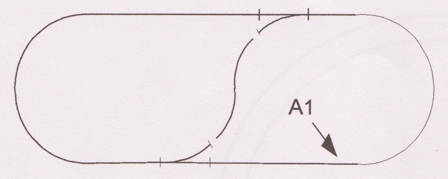
This setup requires two points to form the reversing loop. In this case, the changeover switch becomes unnecessary because switching is carried out by the points, simplifying operations. Both of these layouts look different but are wired in a similar manner. The extended loop of track in the first is reduced to a short length of track in the second.
No changeover switch is required, but it’s still necessary to reverse the polarity of the controller while the train is located in the loop. A change in the direction of the train always requires a change in the polarity of the supply direction on DC control.
Operation
Both points are set to the through position (figure adjacent) and the polarity of the supply to the main line rails is appropriate for a train moving from left to right.

Insulating rail joiners replace metal joiners in four places and wiring links are required between some of the points if using Hornby or Peco SetTrack. The tracks, which form the toe of the frog, must be linked as shown. Peco Electrofrog points are pre-connected so these links aren’t necessary. Insulated track joiners are used at two locations on each point, as indicated.
Power can be connected to the track anywhere at A, B or C on the through-route.
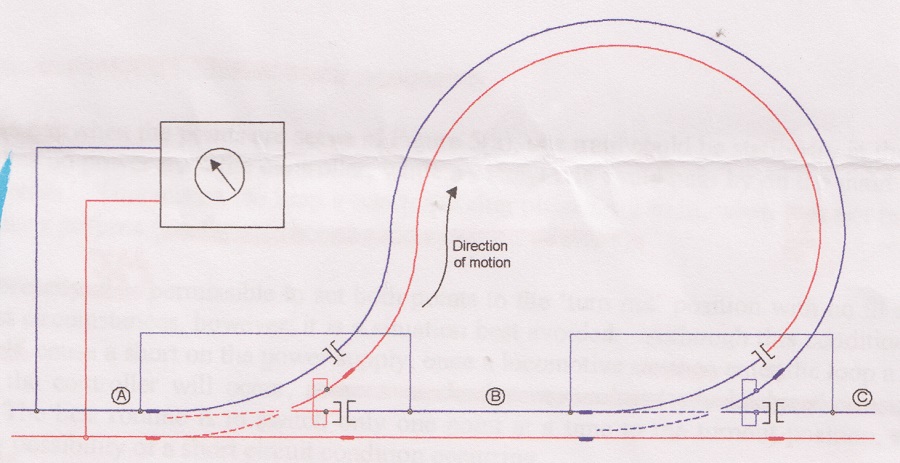
The left-hand point is set to allow a train moving from left to right to enter the loop. The polarity of the supply to the loop has been set by the switch contacts on the point. With the train in the loop, the controller is returned to zero. The left-hand point is set to the through position. The train is parked in the loop and another train could use the main line in either direction.
The right-hand point is changed and the controller is turned in the opposite direction to that used on entry allowing the train to exit the loop.
Both points can be set to the ‘turn out’ position with no ill effects under most circumstances, but it’s best avoided – it won’t cause a short on the power supply, but will once a locomotive enters the loop. The best routine is to switch a point at a time to the turnout position avoiding short circuits. The sequence of actions to operate the loop is easily mastered and mistakes are less likely than with the simple loop.
Reversing loops in use
Apethorne Junction is an O gauge exhibition layout that has made clever use of a reversing loop. The double-track section acts as if it were a junction, allowing trains to return to public view quickly after they reach one end. Rolling stock is almost always on display because both sides of the station are used where halts can be performed. Space inside the loop has been used too with a large mill building. The other end of the layout uses the more traditional fiddle yard setup at a large 10ft in length.

More information
Need some trackplan inspiration? Our article here offers a variety of trackplan ideas for different levels of difficulty.
Looking for some tips in laying track? Our useful guide provides the basics to help you get started.
Need more advice? Take a look at the BRM Techniques page for all our latest guides and advice articles.