The OO gauge ready-to-run market has seen a fortunate influx of models in recent years. Quick to adapt, some forward-thinking kit manufacturers have seen potential in offering new bodyshells of 3D-printed or etched metal construction, which re-utilise RTR locomotive chassis. The result aims to provide accessible locomotive alternatives, while maintaining all the running qualities of RTR models.
If discarding the entire bodyshell of a recent locomotive purchase seems a step too far, other solutions to make your model stand out from the crowd exist, such as an adaptation kit. This contains parts to substitute on your RTR locomotive, transforming it into a non-mass-produced, yet still authentic, variant.
I’ve opted for a kit from Planet Industrials, which transforms the Hattons 0-4-0ST Andrew Barclay with low-sided tanks into one of several variants of the prototype with shorter cabs, employed at Devonport Dockyard. Parts supplied consist of a 3D-printed cab and etched plates and the conversion is mostly removing parts from the RTR cab and swapping them across. Re-painting the entire model is advised, but not essential if modelling a freelance locomotive. By the time I’d removed the pre-painted and glued handrails from the RTR locomotive, with glue blobs to their ends, it was easier to replace them with fresh wire from Albion Hobbies, than clean them up. All told, the kit is a very straight-forward component in what could be considered a small puzzle – taking the RTR locomotive apart, that is. The entire process took me a day, but this isn’t a race. Most importantly, it was an enjoyable process and one that saw me disassemble an intricate detailed model and discover how it was cleverly designed.
1
There’s no denying this is a fine model and it almost seems a shame to alter it, but in the name of individuality, I’m proceeding. Colour instructions highlight the location of accessories provided and motor access.
2
Only the cab must be removed, but in order to get to this, first the chassis must be removed. Access is gained by removing the screws fore and aft underneath, with a cruciform screwdriver.
3
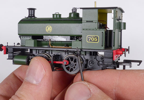
Next, the side lubricator pipes joining the chassis and body must be freed. These injection-moulded items are fragile and so must be handled with care. Gently pull on the tab section, then lever away with tweezers.
4
Steam pipes must also be manoeuvred out of position, otherwise they foul on the locomotive brake rigging. A little prying being careful not to damage surrounding paintwork is necessary.
5
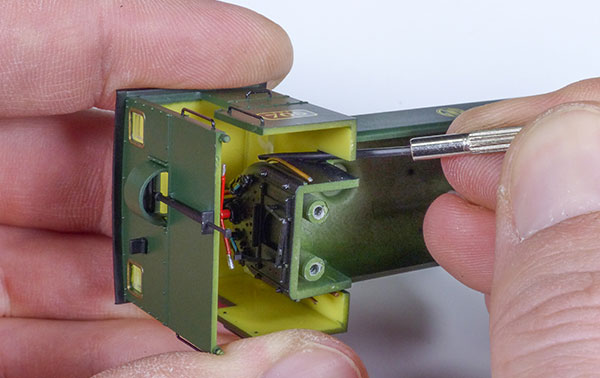
A further three screws must be removed to part the plastic tank and cab from the diecast chassis. All are simple to remove and gave little resistance compared to some RTR models. Two are located under the cab…
6
…the other to the front. Keep all components removed in a small plastic bag and retain inside the original box to prevent loss of parts.
7
A little gentle persuasion sees the two elements separate. Even at this stage, work carefully to minimise damage to the fragile cab interior detail and handbrake mechanism.
8
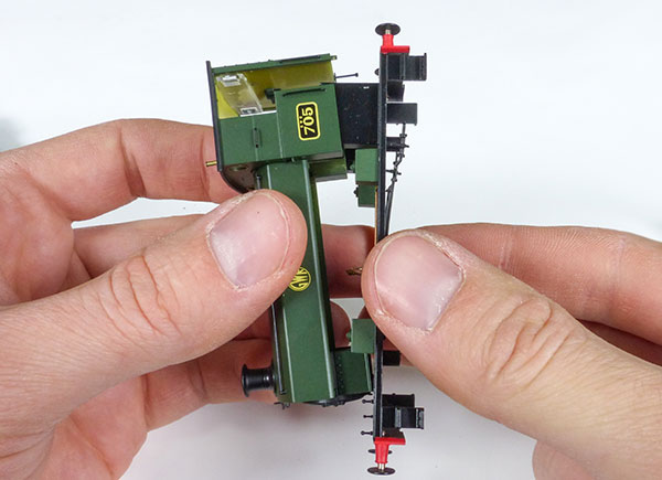
What might puzzle some is the way in which the cab and tank are attached – not by glue, but via two discreet, yet stubborn clips, located either side of the tank curvature.
9
Unclipping the two is best carried out by placing a flat screwdriver at an angle as illustrated and gently applying leverage. This fast-assembly method is efficient during model production.
10
Comparing cabs. The replacement (left), from Planet Industrials is of welded construction and has different window design from that supplied on the model to the right.
11
Instructions for the kit recommend removing components from the RTR cab, and transferring them to the 3D-printed cab. Handrails are easily removed by gently levering with a flat-bladed screwdriver.
12
The plastic rear lamp bracket and handbrake wheel have small spigots, glued to the cab. To avoid damage and to ensure components part freely, pressure must be applied behind each one.
13
Using a fine-pointed steel awl, provided with a set of jeweller’s small screwdrivers, a generous amount of pressure is applied to each lug, supporting the cab behind. Parts crack when freed.
14
The plastic tabs of the handbrake cover must be retained as these clip into the replacement cab. Gently apply leverage with a flat-bladed screwdriver, pushing towards the centre of the part and outwards.
15
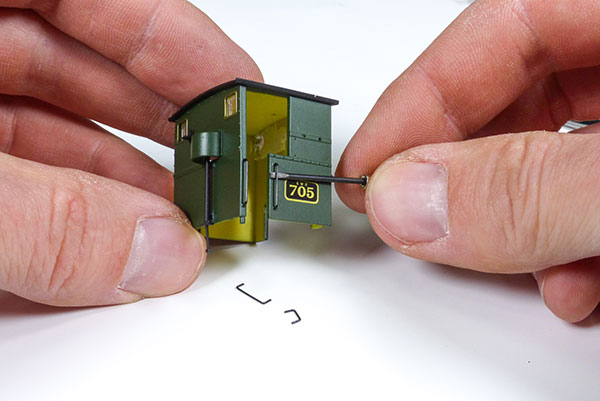
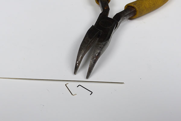
If one of the old handrails is distorted beyond repair, 0.45mm nickel silver rod from Albion Alloys is a useful substitute. An old handrail serves as a template, bending the rod with pliers to suit.
16
Smaller details are returned to the cab. The cab is 3D-printed and so a solvent plastic adhesive isn’t effective. I use a general-purpose superglue with a fine tip applicator from Deluxe Materials.
17
If your gluing skills aren’t nimble, an easier method of application is to dispense a small amount of glue to scrap packaging and apply a dab to the lugs of each part using a worn-out needle file.
18
Supplied with the kit is a neat etched cab roof hatch. It’s important that the part is glued centrally, however, so a centreline is measured and marked.
19
A trial fit of the cab highlights potential fit and finish problems. It has distorted as it cooled from the printing process, but the rear of the cab has lugs, which straighten it out when fitted to the chassis.
20
Respraying the model requires all surfaces to be as flat as possible. The tampo-printed GWR ‘shirt button’ roundel will show underneath paint unless flattened with 2000 grit emery paper.
21
A previous attempt by the manufacturer to correct a hole in the cab roof with filler has failed. This could be repaired similarly, but the angle is exposed, leaving little surface area for filler to ‘key’ onto.
22
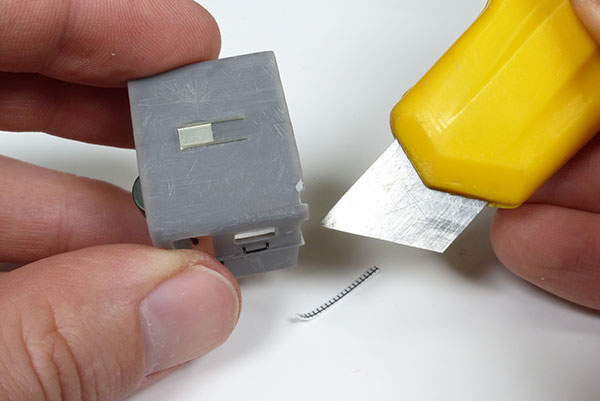
Using a craft knife, the damaged cab roof lip is cut back, flush with the cab front. Cutting edges square will make fitting an off-cut of plastic sheet easier to install. It’s a little like car bodywork…
23
Small amounts of the plastic repair piece are sliced away through much test fitting. Superglue with a fine tip applicator serves as a useful filler too, if allowed to dry between applications.
24
Gently, the small piece of plastic is filed flush with a 800/1000 grit sanding stick. It’s advisable to rotate the component around when doing this, checking for imperfections from all elevations.
25
Spraying the most visible of parts is recommended, but to save time, smaller areas will be brush-painted because this small industrial is to be weathered. Mask areas with tape to prevent overspray.
26
I’ve opted for Lifecolor British Railways BR Maroon, spraying it with an Evolution airbrush. The acrylic paint dries quickly, so I’m working fast to prevent the nozzle from clogging.
27
Smaller and harder to reach areas can be brush-painted. Use a fine bristle brush to reduce the risk of lines appearing when it dries. The key to a successful finish is to remove all traces of dust beforehand.
28
Final assembly of the model is required before a final weathering with the airbrush and Lifecolor acrylic paints from its rail weathering set. I’ve opted not to line the locomotive to represent it as it might have been in service at Devonport, but as it might have appeared if sold on to private industry in a more simplified livery.
Though it looks a complex conversion, this kit greatly simplifies work, leaving surface preparation and a repaint the only potential ‘challenge’. For modellers seeking variety to their Andrew Barclay locomotive fleet, I can recommend it.