16 June 2020
|

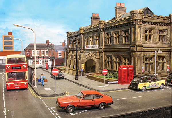
Assisted by recent RTR AC electric releases, this exhibition layout by Carl Bowden blends overhead line electrification observation with British Rail operational practice.
Factfile
Layout name: Alderford
Scale/gauge: 4mm:1ft / 1:76 / OO
Size: 37ft 3in x 2ft
Era/region: BR North West (1985-1990)
Layout type: End to end
When the time came for me to start thinking about building a new layout, I was wanting to do something different from my two previous layouts, both of which were of the round and round kind, ‘Scotforth Junction' in N gauge followed by ‘Great Endon’ in OO.
While on the lookout for ideas and having some criteria in mind (a terminus station and overhead electrification to name two), I came across an article in BRM's sister magazine Traction Annual 2009/10, featuring ‘Liverpool Lime Street’ in the years of 1985/86. The idea that came from reading this article and studying the photographs was to model the operation methods of Lime St. but within the confines of a station with only five platforms, and from this the seeds for 'Alderford' were sown.

From idea to reality
With the help of a former Preston club member, the trackplan was created using a free trial version of Anyrail layout planning software. Once we were happy with the plan, construction was started on the layout in early 2011.
The track was barely laid on the baseboards when I was given the invite form for 'Alderford' to attend its first exhibition in 2013 by the Preston club exhibition manager. Being a member of the Preston club may have helped get this first invite, but also this set the time scale for having the layout in a presentable state before its first show.

Construction
The biggest lesson I learned from my last layout was to not use chipboard for baseboards.
For 'Alderford' I decided to use 12mm marine grade plywood sheet for the baseboard surface and 15mm ply for the framework. A total of nine 4ft x 2ft baseboards make up the layout, 24ft for the scenic section and 12ft for the fiddle yard, plus a 2ft x 15in extension for the station building and street scene. All of the legs for the layout are hinged underneath and each baseboard section piggybacks off the last.
Track work is all Peco Code 75 with live frog points. These are a must in my opinion for the absolute minimum of power interruption, even with DCC control and locomotives manufactured to today's modern standards with all-wheel pick-ups.
'Alderford' Station
Buildings and structures on 'Alderford' are a mixed bag of scratch-built, kits and ready-to-plant items. Starting with the low-relief buildings on the backscene, the church and the office block for the industrial area are scratch-made from flat sheets of clear Perspex with added brick or stone embossed sheet, raised detail, and then painted. The church also has a working clock face added into the tower for that extra finishing touch. The remaining low relief buildings are from either Ten Commandments or the Skytrex range.
The locomotive maintenance depot shed, office block, disused signal box and the low-relief corner pub by the station building are from the Bachmann Scenecraft range.

The station building, of which I get asked quite often about at exhibitions, is from the Townstreet Models range of cast resin kits and is loosely based on the main building of Carlisle Citadel station. Finding an impressive station building for 'Alderford' was a bit of a concern at the start, as I was not liking a lot of what was on the market, either ready-to-plant or in kit form and was thinking that this was also going to be a scratch-build job. It was only by chance that I spotted a small advert in the back of a magazine for Townstreet Models with a photograph of the built station kit and that was it, my search was over - it was the perfect station building for 'Alderford', despite the near £100 price tag! Room interiors are being fitted to the building, but this is still an ongoing job.
The train shed for the station is Peco, using four kits to make the 3ft 8in twin-arch structure. Originally, I also used the support pillars that came in the kit for the middle, the two sides being supported by brick arched walls, but within the last 12 months, they were replaced with much more robust brass tube pillars, support beam and ornate bracing at the top of the pillars. Changing the pillars to brass tube also allowed me to attach working lamps to them. The train shed roof lifts off to facilitate access to clean the track and re-rail derailments.

The power feeder shed for the overhead line equipment is the only scratch-built full building on the layout built for me by John Wilson. He was on the job of building one of these sheds for the club layout, so I thought he may be happy to build a second one for 'Alderford'.
Live wires?
The Overhead Line Equipment (OLE) is probably the biggest single feature on 'Alderford' and is the subject of most of the questions I get at exhibitions, including “are the wires live?” The wires are not live, but one stipulation was that all pantographs on electric locomotives had to run up against the wire. I'm not really a fan of pantographs being held just short of the wire.
The vast majority of the support structures are of the multi-track head span type. These had to be built in-situ, first by driving in the 4mm 'H' section in to 3.5mm drilled holes in to the baseboards. Then all of the wires, insulators and catenary arms were attached with the help of a marked-up block of wood that sat on the track to make sure that the catenary arms were positioned correctly.

The actual catenary wires are from the Sommerfeldt range, as are the single arm masts used at the end of platforms 1 and 2 and along platform 5. 'Alderford' was built just a few years too early to benefit from the introduction of the Peco OLE system.
I have also fitted springs to the two ends of the OLE system just beyond the bridge as part of the wire lead on/off ramp and at the ends of each platform to apply tension to the whole system to prevent too much up and down movement of the pantograph as it runs along the wire. The wires are also zig-zagged along the length of the layout to even out wear on the pantograph contact shoe.
The majority of my electric locomotive fleet and EMUs have all been fitted with Sommerfeldt pantographs as I just find they work better than the factory-fitted offerings and all of them have had the pantograph arm spring tension reduced to lower the upward force against the wire.

The exception to this is the newly-introduced Bachmann Class 90 with its working servo-driven pantograph, which when in the up position is already very softly sprung. This is a very welcomed feature that gets made use of a lot on 'Alderford' whenever a Class 90 is stabled waiting for its next turn.
Layout operation
'Alderford' is operated by a team of up to six people, the signalman, the station pilot, two operators at the station, one bringing in arrivals, the other on departures and the last two operators working the fiddle yard.
With 'Alderford' being set in the mid- to late-1980s, a form of BR inefficiency is applied. A typical locomotive-hauled train movement would start by being sent from the fiddle yard by one of the fiddle yard operators to emerge from under one of the two bridges. As the locomotive travels along the layout, its control is handed over to the station operator dealing with arrivals.
Once the train arrives at the station, the locomotive is uncoupled from the train with the aid of magnets triggering Kaydee couplings and is then classed as trapped at the buffer stops.
If all is running to plan, the station pilot operator will have got another locomotive ready to drop on to the rear of the train that has just arrived.

When the train departs from the station this will release the locomotive that was trapped at the buffers. At the likes of Liverpool Lime Street it was common for this locomotive to follow the departing train quite soon after as far as the signal at the end of the platform and this is common practice on 'Alderford'. When cleared to do so, the locomotive will then proceed to the stabling point to wait its next turn.
Obviously, all this has to be fitted in with the other frequent train movements like DMUs, EMUs or even an HST coming and going.
At least half of the locomotive, DMU and EMU fleet is DCC sound-fitted and this enhances the operational experience, from locomotives stabled on the depot being shut down and started up, to the door beeps and guard to driver buzzers on the multiple units.
Operating on 'Alderford' can definitely keep your mind occupied for hours.